| COMP1011 Assignment 2 - 05s2 | |
|---|---|
| Computing 1A 05s2 |
Last updated
Tue 13 Sep 2005 22:50
Mail cs1011@cse.unsw.edu.au |
In fact, even to solve the bonus part of the assignment, you don't have to
understand all the details described below. However, you will find them
helpful if you try to understand some of the code in the module
RayTrace.hs. This page is an extended version of the page
entitled The World and its Physics - the
basics.
Much of this section is written in mathematical notation, not the
notation that will be used within the Haskell code. We distinguish
the two by using different fonts. Mathematical equations will be
denoted using the italic font while Haskell code will always
be in the typewriter font. We define many terms in this
section in a mathematical style. There is of course a Haskell
counterpart to many of these concepts and most of them appear in the
Physics module.
The world is the setting in which we compose scenes in. A scene can contain two types of objects: spheres and planes which are explained a subsequent section of this document.
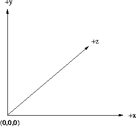
A point within the world is described using three-dimensional cartesian co-ordinates: a triple of values, (x,y,z). The co-ordinate system is left-handed meaning that the if we orient the world such that the x-axis points right and the y-axis points up then the z-axis points away from the viewer (or "into the page").
Each scene is contained within a volume element or voxel. This is simply a fancy name for a cube which bounds the scene. A voxel is defined by its left/bottom/front corner, a point, and the length of its side. This can be written as a pair. e.g. ((1.0, 2.1, 3.0), 5).
A computer monitor is composed of a rectangular array of so-called pixels; an abbreviation for picture element. The colour of each pixel is composed of three components; a red, a green and a blue one. In this assignment colours will be represented as a triple of double-precision floating-point numbers of the form (r,g,b) where r,g, and b are between 0.0 and 1.0 inclusive.
For example the brightest possible red a computer can display is (1,0,0), while a very dark blue would have the value (0,0,0.1). (1,1,1) is the colour white, while (0,0,0) is black.
A vector is used to represent a direction and is represented as a triple of floating-point values. For instance, (0,0,1) is a vector pointing in the direction of the z-axis.
Vectors also have a magnitude
(or length). For a given vector, (v1,v2,v3), the magnitude is
defined as sqrt (v1^2 + v2^2 + v3^2). A unit vector is one that has a
magnitude of one. A unit vector can be obtained from a regular vector
by dividing each component of the vector by the magnitude. For
instance, let m = magnitude (v1,v2,v3). Then a unit vector
point in the same direction would be (v1/m, v2/m,
v3/m). However, we have provided a function unit in
module Physics that does this
for you.
In the rest of this section vectors are either written as triples or using a single capital letter. In this case the letter will be in bold. e.g. N
A ray consists of a point, called the origin of the ray, and a vector, called the direction. The origin of a ray should not be confused with the origin of the world which is the point (0,0,0). A ray is a function from time to points. For example: R(t) = (1,2,3) + (4,5,6)t
This ray has an origin of (1,2,3), equal to R(0), and a direction of (4,5,6). Note that the first is a point while the latter is a vector. There is no difference in their representation, yet they are used for very different purposes.
The intersection of a ray with an object is expressed as the time of intersection rather than a point. This makes sense since if we expressed it merely as a point there is no guarantee that it would actually lie on the ray. For example, the ray, R(t) = (0,0,0) + (1,2,3)t has value (2,4,6) at time t=2.
The functions rayAt, rayOrigin and
rayDir in module Physics are useful for manipulating
rays.
There are two types of objects that can appear in a scene, planes and spheres. The Haskell data type for representing these pure objects is:
data PureObject = Sphere Point Distance
                | Plane  Distance Vector
A close real world example of a plane is a flat piece of paper that extends infinitely in all directions. They can have any orientation and be arbitrarily far way from the origin of the world. However, for the purposes of this assignment they shall only extend as far as the bounds of our world. To put it another way, planes do not extend outside the voxel containing the scene. Planes are represented as a distance and a unit normal vector, which we have not defined as of yet.
A normal vector is one that points in the direction that is perpendicular, or at 90 degrees to, all the points in a plane. It is therefore natural to define a plane in terms of a normal vector. However, as we shall see later they are vitally useful for describing the angle at which a ray strikes and reflects from an object. Another thing that should be mentioned is that a normal vector for a plane can point in two directions, one for each side of the plane. The side of the plane from which the vector emerges is known as the positive half-space of the plane; the other as the negative half-space.
The unit normal vector of the plane points towards the origin of
the world. For example, the plane, Plane 10 (0,0,-1) is
parallel to the x-y plane but a distance of 10 units along the
z-axis.
Spheres are much easier to conceptualise in the mind. They have a centre (represented as a point) and a radius (a distance). The surface of a sphere is that collection of points that lies uniformly distant from the centre.
Each pure object in the scene has some associated properties:
colour, diffuse reflection coefficient and specular reflection
coefficient. (The meaning of the two reflections coefficients will be
covered in the Reflections section.) These objects are modelled in the
Physics module with the following data structure:
  data Object = Object PureObject
	               Double  -- diffuse reflection coefficient
                       Double  -- specular reflection coefficient
	               Colour -- colour
Lights in a scene have two properties: position and colour. They are assumed to emit light uniformly in all directions.
The position of the eye is fixed at the co-ordinates (0,0,-1) and it points directly down the z-axis. The dimensions of the view plane are determined by an angle known as the field of view. This angle is measured in degrees, not radians, and represents the angle formed between a line from the ray to the left and right hand sides of the view plane. The view plane is measured in terms of world co-ordinates and although this is the case it corresponds to the final image to be rendered (in pixels).
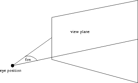
The final image to be rendered is something that will be displayed on a computer display and as such must be measured in terms of pixels. (See the section on Colour for a more in depth explanation.) Given the final dimensions of the rendered image, (imWidth,imHeight) we can calculate the dimensions of the view plane, (vpWidth, vpHeight)
vpWidth = 2 * tan (0.5 * fov * pi / 180)
vpHeight = vpWidth * imHeight / imWidth
For example say you wish to render an image of size (640,480) where the field of view if 60 degrees. Then the view plane has its top-left corner at (-0.57735, 0.43301), has a width of 1.15470 and a height of 0.86603
pixelWidth = vpWidth / imWidth
dir = (x + (i + 0.5)*pixelWidth, y - (j+0.5)*pixelWidth, 1)
unitdir =unit vector in same direction as dir
R(t) = (0,0,-1) + unitdir*t
You will be writing a function which calculates rays from the eye position to point corresponding to a pixel in the final image
Objects in the real world reflect light in different ways. Some objects scatter the light that strikes them uniformly in all direction while others reflect light only at an angle equal to the angle of incidence. The former is known as diffuse reflection while the latter is known specular reflection. Each object within the world has a surface that reflects in a manner that is either diffuse, specular or both.
In the following sections we refer to the following diagram many times. It shows the light from the eye position (labelled as Viewer in the figure), the point of reflection, a vector pointing towards a light source, a normal vector at the point of intersection, a vector half way between the light vector and the one from the eye, and a ray, S, leaving the surface at the same angle at which the ray from the eye hits it.
Ambient light is just a base level of light in a scene. In the real world it is that light which comes from the millions of reflections on all the objects around you. Even if there are no light sources in a scene, each object will be lit to by ambient light.
intensity = kdIaC
where:
The diffuse reflection coefficient, kd is a number in the range [0.0, 1.0]. An object that reflected all the light upon it would have kd = 1.0, while one that absorbed it all would have kd = 0.0.
You will be writing a function to calculate the ambient contribution to the light entering the eye.
Many real world objects have surfaces that are not entirely smooth and as a consequence reflect light evenly in all directions. We can calculate the intensity of the light (from the jth light source) reflecting from an object using the following equation:
intensity = kd(N · Lj)IjC
where
The reasoning behind this equation is as follows. The intensity of light striking the surface is proportional to the cosine of the angle between Lj and N. A light source that sits directly above an object illuminates it more strongly than one that shines on a surface from an angle. This can be found by taking the dot product of the vectors N and Lj. (Be careful! This only works if they are unit vectors.)
The intensity of the light, Ij, is attenuated over distance.
Ij = (100 / (99 + d2))Bj
intensity in module Physics.
But this is not all! It is also possible that Ij is equal to the colour black. This happens when the light source is behind the object or there is another object between the light source and the surface. See the section on shadow rays for details.
You will be implementing a function that returns the component of the light from diffuse reflections.
Specular reflections are those that occur on shiny, smooth surfaces. Light rays upon such surfaces reflect off the surface at precisely the angle they strike the surface. In other words, the angle of incidence is equal to the angle of reflection. But as for diffuse reflections we must also work out what the intensity of the light striking the surface must be. This time, however, we do this by taking the dot product of the normal and a new vector that lies half way between the ray from the eye and the ray to the light. We call this vector Hj. The rest of the values in the equation below are the same as for diffuse reflection above.
intensity = ks(N· Hj)IjC
Also, note that the ray from the eye, Hj and Lj all lie in the same plane. You will find this fact useful for calculating Hj.
You will be implementing a function that returns the component of the light from specular reflections
It is also possible that an object is illuminated by light from
other objects; moonlight striking the surface of the Earth is a good
real world example of this. It turns out that this component of the
light entering the eye is probably the easiest to calculate. We simply
recursively call the ray tracing algorithm upon a ray that leaves the
object at precisely the same angle the ray from the eye strikes
it. This is ray S in the diagram above. This angle is
calculated by finding the angle between the ray from the eye and the
normal. We have provided a function in the Physics module
called angleBetween that should be useful.
The value returned by recursively calling the ray tracing algorithm is then multiplied by the specular reflection coefficient. The final equation is
intensity = ksIsCwhere Is is the result of recursively calling the ray tracing algorithm on the ray S in the diagram above.
You will be implementing a function to find the light reflected from other objects
In the above sections on diffuse and specular reflections we have deferred discussion of two very important cases. What if the light source is:
Fortunately each of these cases is fairly easy to solve. A simple way to check whether the light source is behind the object is to find the angle between the normal vector N and the vector pointing towards the light, Lj. If it is greater than pi/2 radians (which is equivalent to 90 degrees) then the light source does not contribute. That is Ij is equal to colour black.
The second case is a little more complicated. If we find that the angle between N and Lj is less than or equal to pi/2 radians we still must check whether the light is blocked by another object. What we must do is shoot a shadow ray from the point of intersection (with the original object) towards the light source and check whether it intersects with any other objects.
You will be implementing a function which a) checks the angle between the normal and Lj (and does the appropriate thing) and b) checks whether shadow rays intersect with objects.
The final equation for determining the colour of the light entering the eye is:
I = kdIaC + kd sumj { (N· Lj)IjC } + ks sumj { (N· Hj)IjC } + ksIsC
The sumj { ... } notation simply means that you must sum over every light source. For example, if there were three light sources the expression sumj { N· Hj } would expand to ( N·H1 + N·H2 + N·H3).
In using this equation one must bear in mind everything that has been stated so far, particularly the fact that shadow rays must be used to check whether light sources contributed to the final colour. It is not simply enough to plug numbers into the equation.