Late submissions will not be accepted after midday monday week 13.
For the second assignment you will be building a 3D world .
This is an assignment you should do in pairs. Pairs should be chosen from the same tutorial class if possible. You will be performing a demo of you work in week13 during the tutorial time or the hour after. You may do the assignment individually if you choose to.
The aim of this assignment is to test:
Furthermore, the assignment is open-ended, allowing you to make additional improvements of your own choice.
Your task is to complete the implementation of a 3D world. In this world you control a camera moving around a landscape which includes trees, hills and roads.
Download a set of base classes here. These classes implement the basic data-structures, but are incomplete. The files provided are:
There is also a org.json file library for level I/O. The level files are fairly easy to read and change by hand.
You are free to change any of these files as you see fit. We will not be testing individual functions. However you should make sure that the established Level IO format works for your code, because we will be testing your level with standard terrain files.
This is the main class for your game. The main() method in this class will be used to test your game. It expects a single string specifying the name of the level file. If you want to specify any other parameters they should be part of the JSON file.
The terrain is represented as a grid. The width and height of the grid are specified in the level file. Each point in the grid has a specified altitude. Your first task is to draw the terrain as a mesh of triangles with vertices at each of the grid points with the corresponding altitude.
You can treat X,Z and altitude as OpenGL coordinates. They should all have the same scale. Test maps will be of the order of 10x10 to 20x20. Maximum altitudes will be in a similar range (10-20).
A 2x2 terrain with altitudes:
Note: the bold labels (x0,x1,z0,z1) are just to explain what the values mean and will not actually be part of the data| x0 | x1 | |
|---|---|---|
| z0 | 0 | 0.5 |
| z1 | 0 | 0.3 |
A 2x2 terrain represents 4 vertices. The altitudes correspond to the Y values for the x,z co-ordinates.
Will create a mesh withe the following co-ordinates
(0,0,0)  (1,0.5,0)
   +-----+
   |    /|
   |  /  |
   |/    |
   +-----+
(0,0,1)  (1,0.3,1)
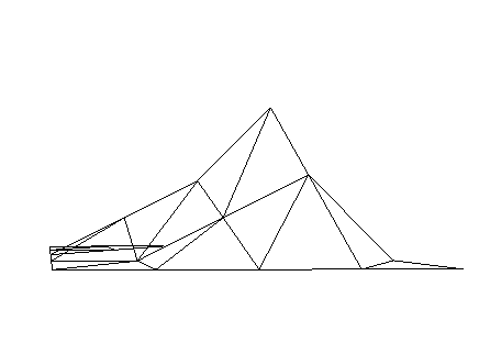
A 5x5 terrain with altitudes:
| 0 | 0 | 0 | 0 | 0 |
| 0 | 0 | 0.5 | 1 | 0 |
| 0 | 0.5 | 1 | 2 | 0 |
| 0 | 0 | 0.5 | 1 | 0 |
| 0 | 0 | 0 | 0 | 0 |
Will create a mesh that looks like this (this may look different depending on the angle/position you view it from and exactly how you set up your camera). This is taken from basically straight ahead at around (0,0.5,9) in world co-ordinates and with a perspective camera:
Note:This screenshot was taken with back face culling on
Note: for the assignment you will shade and texture your terrain and make it look pretty. We are just showing the lines here so you can clearly see the geometry. It is up to you whether you implement your terrain using face nomals or vertex normals.
The levels include trees at different points on the terrain. Your second task is to draw the trees at the specified locations.
For the base version of this project, a tree should be a simple mesh with a cylidrical trunk and and a sphere of leaves. If you want you can make your 'trees' more exotic: lampposts, candy-canes, chimneys, or whatever your imagination dictates. The point is that they are placeable 3d models on the terrain.
Note that the level descriptions only specify the (x,z) location of the tree. You will need to use the terrain data to calculate the altitude of the tree and draw it appropriately. Trees are not guaranteed to be positioned at grid points, so you will need to interpolate altitude values if a tree is in the middle of a triangle.
The level include roads. Each road is described as a 2D Bezier curve. I have provided a function for you which calculates the (x,z) location of points along the road. Your third task is to use this function to extrude a road which follows this curve, with the width specified in the constructor.
You can assume, for the base portion of the assignment, the roads will only run over flat terrain, so you will not have to handle going up or down hills.
You should implement a 3D camera which moves around the scene using the arrow keys:
The camera should move up and down following the terrain. So if you move it forward up a hill, the camera should move up the hill.
The camera should be a 3D perspective camera with a reasonable field of view. The aspect ratio should match the aspect ratio of the viewport.
You should render the scene with appropriate materials and lights. In the base version you should at least have a single light source representing the sun. The terrain, trees and road should all have suitable materials.
The level files include a "sunlight" field which is a 3D vector specifying a directional light to be included in the scene. The vector represents the direction to the source of the light.
You should texture all the models (terrain, road, trees,avatar,others) in the scene, using MIP maps to handle minification. You may use whatever textures you feel suitable. Be creative. Make everything look like Lego or ice sculpture or origami.
The base elements described above are worth 19 of the 25 marks. For the remaining 6 marks you can choose among the following extensions:
For the full marks this would need to include alpha blended billboarded particles, creation and destruction ,some kind of evolution over time (position, size, colour, as is appropriate for your kind of particles).
Ponds need only lie on flat terrain like roads but should include animated textures showing ripples or waves.
To get full marks for this you would need to implement a proper rewite system. You would not need to load the grammar for the L-system from JSON, but it should be possible to alter the grammar just by changing values in the code.
You should also provide a way to increase/ decrease the number of iterations either interactively or from reading in the number of iterations from a json file. By default you should set it to the number of iterations that looks best/runs best. It does not matter if the tree does not look as good when iterations are increased/decreased. It is also ok if performance drops for high numbers of iterations. This is to be expected.
If you have other ideas for extensions please ask on the forum. If there are any I like, I will add them to the list. I'm looking for extensions which test your use of different rendering techniques rather than just adding more stuff to the world.
Note: The marks above increase roughly logarithmically with the amount of work required. So a task worth 6 marks is about 16 times harder than a task worth 2 marks.
This assignment is worth 25% of your final mark. Marks are assigned as follows:
| Item | Marks |
|---|---|
| Terrain - mesh generation | 2 |
| Terrain - interpolating altitudes | 1 |
| Trees - mesh generation | 2 |
| Road - mesh generation | 3 |
| Camera - perspective projection | 1 |
| Camera - movement | 1 |
| LightingĀ | 2 |
| Textures | 2 |
| Avatar | 2 |
| The others | 3 |
| Extensions | 10 |
The extension element includes 4 bonus marks, so the maximum possible mark is 29/25.
Marks beyond 25 will only be awarded if all the base components work appropriately. You can not make up for marks lost in the core component with marks from the extension component. For example, if you lose 2 marks in the core component, the most you can get is 23/25.
Submit a single JAR file containing all your Java source and any addition files needed to make your project work.
Notes:
Submit your JAR file using CSE give, either using webcms or the command line:
% give cs3421 ass2 Ass2.jar
Late submissions will lose 2.5 marks per day from the maximum possible mark.
Submissions will not be accepted after midday monday week 13.
Sample world file: Test 1
{
    "width" : 10,
	"depth" : 10,

	"sunlight" : [ -1, 1, 0 ],

	"altitude" : [
	    0, 0, 0, 0, 0, 0, 0, 0, 0, 0,
	    0, 1, 1, 1, 1, 1, 1, 1, 1, 0,
	    0, 1, 1, 1, 1, 1, 1, 1, 1, 0,
	    0, 1, 1, 2, 2, 2, 2, 1, 1, 0,
	    0, 1, 1, 2, 3, 3, 2, 1, 1, 0,
	    0, 1, 1, 2, 3, 3, 2, 1, 1, 0,
	    0, 1, 1, 2, 2, 2, 2, 1, 1, 0,
	    0, 1, 1, 1, 1, 1, 1, 1, 1, 0,
	    0, 1, 1, 1, 1, 1, 1, 1, 1, 0,
	    0, 0, 0, 0, 0, 0, 0, 0, 0, 0,
	],

	"trees" : [
		{
			"x" : 1.5,
			"z" : 1.5
		},
		{
			"x" : 4.5,
			"z" : 4.5
		}
	],

	"roads" : [
		{
			"width" : 3,
			"spine": [
				1.5, 3,
				1.5, 0.5,
				7.5, 1.5,
				7.5, 1.5
			]
		}
	]

}
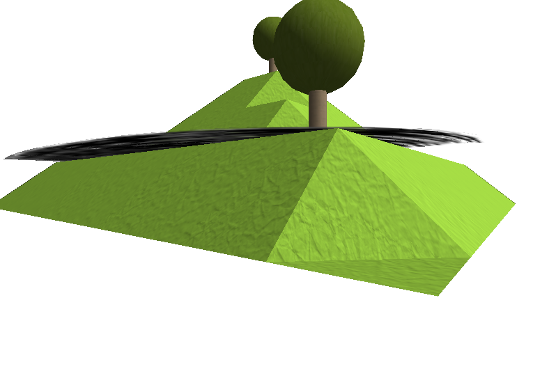
is the shot of Test 1. The road goes over the edges of the terrain.
You can see more examples here.