Week 12 Tutorial Solutions
Question 1: Radiosity
Consider the 3x3 room below.
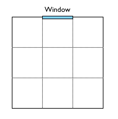
We want to use radiosity to light this room. We shall consider each wall to be made of three equal size patches. For the sake of this exercise we will work in 2D only.
We can use the Nusselt Analog to compute the form factors between patches:

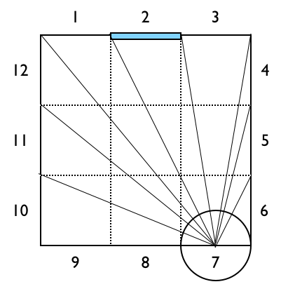
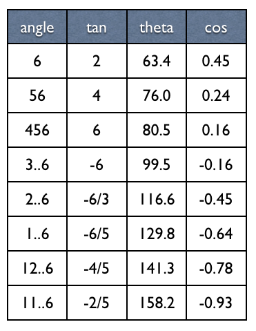
The image above illustrates the computation for F[8,5], below
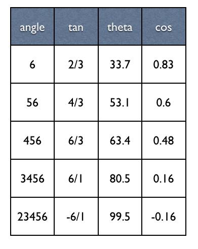
tan(theta) = 1/1.5
theta = 33.69°
cos(theta) = 0.83

tan(phi) = 2/1.5
phi = 53.13°
cos(phi) = 0.6

F[8,5] = (cos(theta) - cos(phi)) / 2
       = 0.12
a) What are the form factors for the other faces. (Hint: you can exploit a lot of symmetry here)
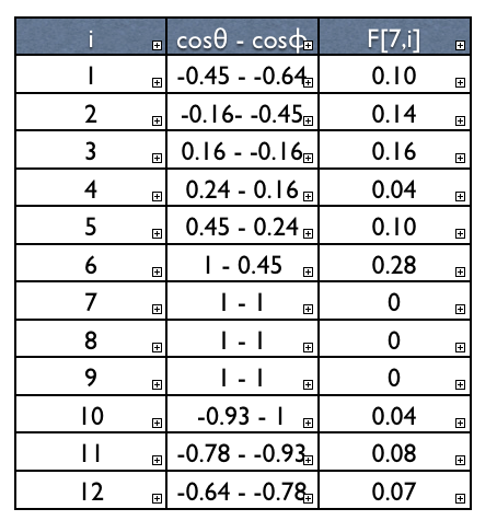
We need only compute form factors for walls 7 and 8. All the others can be obtained by symmetry.
As shown in the example F(i,j) equals (cos(theta) - cos(phi)) / 2.
We can compute these cosines from the dimensions of the image. For wall 8:
The rest can be computed by symmetry.
This provides form factors:
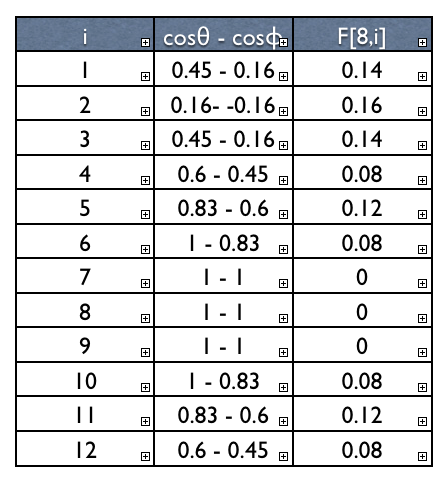
Similarly for wall 7:
Suppose the window (patch 2) has emmissive energy E[2] = 1 and diffuse reflection coefficient rho[2] = 0
All the other walls have E[i] = 0 and rho[i] = 0.5.
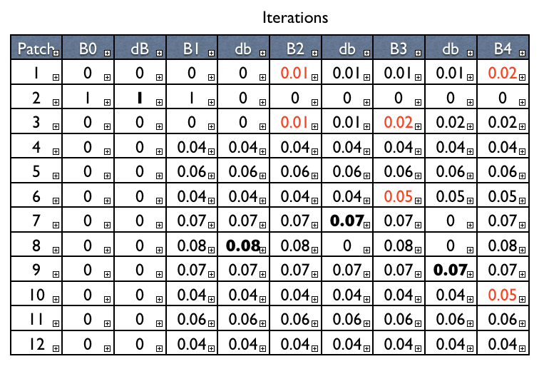
b)Use four iterations of the progressive refinement algorithm to compute radiosity values for the walls.
The progressive refinement algorithm is shown below. It prioritises patches by how much light they have stored up.
for each patch i:
    B[i] = dB[i] = E[i]

iterate:
  select patch i with max dB[i]:
  calculate F[i][j] for all j
  for each patch j:
    dRad = rho[j] * B[i] *
           F[i][j] * A[j] / A[i]
    B[j] += dRad
    dB[j] += dRad
    dB[i] = 0
Note:Nusselt's Analog computes the form factor Fij for light entering the patch i from every patch j.
To compute the form factor Fji for light sent from patch i to patch j, we use the equation
Fji = Fij Aj/Ai
Now the table below summarises the application of four iterations of the progressive refinement algorithm. The bold entry in each dB column indicates the patch with the maximum amount of stored energy (walls 2, 8, 7, 9), which is spread in the next iteration.
The red values in interactions 2, 3 and 4 show the walls which have significant radiosity change as a result. In this example the effects are relatively small, because the initial light source isn't very bright.
Question 2: Rational Bezier Splines
Evaluate the co-ordinates of a unit circle, with the centre at (0,0) defined by the parametric equation for a circle
x(theta) = cos theta
y(theta) = sin theta
with theta = 90 and theta = 210
Show how a degree 2 rational Bezier spline with the control points and weights in the table below can
represent a unit circle at centre (0,0).
Evaluate the co-ordinates of the circle at theta 90 and 210 by using equivalent values of t and the relevant rational bezier
spline equations.
| Control point |
Weight |
| (0, -1) |
1 |
| (-sqrt(3), -1) |
0.5 |
| (-sqrt(3)/2, 1/2) |
1 |
| (0, 2) |
0.5 |
| (sqrt(3), 1/2) |
1 |
| (sqrt(3), -1) |
0.5 |
| (0,-1) |
1 |
Evaluating
x(theta) = cos theta
y(theta) = sin theta
with
-
theta = 90 gives us point P(0,1)
-
theta = 210 gives us point P(-0.866,-0.5)
The spline consists of three curves each forming a third of the circle.

Each are degree 2
rational bezier curve with equation:
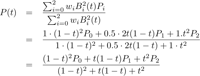
The equivalent point at theta = 90 would be t = 0.5 on the curve with control points
P0: (sqrt(3)/2, 1/2) P1: (0,2) P2: (-sqrt(3)/2,1/2)
Substituting those values into the equation above should give us P = (0,1)
The equivalent point at theta = 210 would be t = 0.5 on the curve with control points
P0: (-sqrt(3)/2, 1/2) P1: (-sqrt(3),-1) P2: (0,1)
Substituting those values into the equation above should give us P = (-8.66,-0.5)
Question 3: Sample Exam Questions
a and b are similar in style to Part B of the final exam which are short answer questions. c,d,e and are similar in style to Part C in the final exam which are design questions
- Explain the advantages and disadvantages of normal mapping (a.k.a. bump mapping) over adding extra polygons to represent detail.
-
Advantages: Every polygon we add to the scene creates extra computation at
every step of the pipeline: transforming, illuminating, clipping,
rasterising, etc. Having a large number of polygons is therefore very
computationally expensive. Normal mapping allows us to represent rough
surfaces with far fewer polygons.
-
Costs: Extra work has to be done in the texturing stage. Normals must be
computed for each pixel on the surface and the illumination equation
recalculated to include data from the normal map. The map itself must be
stored in memory, doubling the amount of texture memory required.
-
Disadvantages: One problem with using normal maps is that they do not
affect the outline of the object. So if the surface is viewed on an angle,
it will appear flat. Also normal mapping only works for minor perturbances
in the surface. Larger bumps should occlude other parts of the suface when
viewed at an angle. Normal maps do not support this occlusion.
- We have looked at three methods for simulating shadows: shadow mapping, ray-tracing and radiosity. What are the pros and cons of each technique? When might they be appropriate to employ?
-
Shadow mapping: is relatively fast and can usually be done in real time.
It requires two extra rendering passes per light source, one to compute
the shadow buffer and one to apply the shadows to the scene. The quality
of the shadows is limited by the resolution of the shadow buffer. A higher
resolution buffer gives better looking shadows but is more costly in terms
of time and memory. Shadow edges are hard and appear jagged at low buffer
resolutions.
-
Ray-tracing: is relatively slow and can only be done in real time on very
high-end machines. For every pixel in the rendered image a ray is cast
from the object hit towards each light source in turn to decide whether
the source is occluded or not. This avoids the quality prolems created by
the shadow buffer, but it much more computationally expensive. The
advantage is that it can take into account reflected and refracted light
and so produces much more realistic lighting. Nevertheless the shadow
edges are still typically hard.
-
Radiosity: takes into account light from all objects in the room, not just
light sources. This means that shadows are much softer and realistic
because it takes into account light from very many angles. As a result,
the computational cost is much higher and this approach is typically not
suited for real-time rendering. However the results of radiosity
calculations can be baked into static light-maps and used in real time
situations if the lights and objects in the scene are not moving.
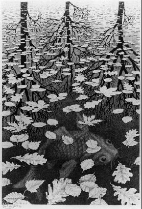
- Below is an image of M. C. Escher's Three Worlds. We want to render a short animation of this scene. What techniques would we employ?
-
Assuming the scene is not intended to be rendered in real time (i.e. it is
a static animation, not an interactive systems) then we are free to use
more expensive rendering techniques to produce high-quality images. One of
the crucial elements of this scene is the water: it reflects the images of
the trees in the distance but it is also transparent and allows the
underwater fish to be seen. This calls for a ray-tracing renderer, which
is able to handle reflections and transparency.
-
The water itself could be rendered using volumetric ray-tracing so that
the light diminishes as rays pass deeper underwater. Snells law could be
used to compute refraction as light passes between the water and the air.
If you look carefully, you will notice the the water is more transparent
in the foreground and more reflective at the back. The Fresnel equations
(not covered in this course) describe this behaviour, the proportion of
light that is reflected or transmitted depends on the viewing angle.
-
The trees in the background could be procedurally generated using an
L-System. The leaves on the water surface could also be generated using an
L-System (although this hasn't been discussed in the course). The fish
would probably need to be modelled by hand.
-
If this were to be animated it would be nice to have the trees move with
the wind and add ripples
on the surface of the pond.
-
Finally, the entire image could be rendered with a non-photorealistic
filter to imitate Escher's original lithograph.
Note: This is a much longer answer than I would expect from you in
the exam. I provide it here to show the variety of things to think about
in rendering a simple image like this. If this were an exam question, it
would focus more on the particular use of ray-tracing to render this
scene.
-
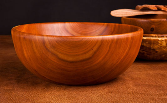
For an art project you need to render a polished wooden bowl like the one below. How would you generate this mesh? What method would you use to texture it? What would its material properties be for lighting?
-
A mesh for this shape could fairly easily be extruded by taking a vertical cross
section through the middle of the bowl and rotating it around the Y-axis (creating a
surface of revolution). To create the effect of the bowl having been carved out of a
solid piece of wood, it would be more appropriate to use a 3D texture of woodgrain
rather than try to wrap a 2D texture around this surface.
-
The bowl shows both specular and diffuse illumination (notice the specular
highlights on the rim and inside the bowl). The specular highlights are broad,
suggesting a low shininess value would be appropriate. Phong shading would probably
be appropriate to ensure that the surface appears curved and highlights are rendered
well. A normal map could be added to give the surface some roughness so that it
doesn't look too glossy.
-
You want to implement a smoky fire in a 3D game. Name (at least) two different approaches to implementing this. What are the pros and cons of each?
-
Volumetric objects like fire and smoke are usually implemented as either
particle systems or using volumetric ray tracing. A particle system
represents the volume as a collection of moving particles. A volumetric
system represents the volume as a grid of cells with varying density.
-
In broad terms, particle systems are easier to implement in
polygon-rendering systems like OpenGL as they can be represented simply as
collections of quads or point sprites, which are generally supported with
little extra coding. Grid-based representations will required more
specific ray-marching code to be written. On the other hand, grid-based
representations are easier to implement in ray-tracing systems, where
particles require lots of individual collisions to be calculated.
-
The pros and cons of particle vs grid-based simulations are actually well
beyond this course. I put it in here as a challenge question to get you
thinking. To learn more about this I recommend the Fluid
Simulation for Video Games articles by Dr. Michael J. Gourlay.
If there is any more time left, please go over material from previous weeks tutorials that were not finished or discuss last minute assignment issues.