Your task is to implement, in Erlang, a simple message router network whose main task is to route simple messages between the nodes that make up the network. In addition to routing messages, the router network needs to support atomic updates of its routing configuration.
The router network consists of a collection of router nodes that are connected to each other by labelled edges, forming a directed, labelled, strongly-connected graph (which we will call the network graph). A message routed through the network starts at one node and is passed on between other nodes over the edges until it reaches its destination node. The nodes are named and the edge labels direct message routing in the network. Specifically, an edge label consists of a set of node names that specify which nodes can be reached by sending a message over that edge. Thus, for example, a node will forward a message whose destination is A over the edge whose label contains A. A node name will never appear in the label of more than one edge leaving a particular node.
The following figure shows an example of a network graph.
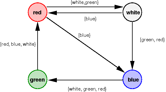
Based on the edge labelling in this graph, a message starting from node red with destination green would be sent from red to white, then from white to blue, and then from blue to green.
The router network also contains a single controller node (not shown in the diagram) that is responsible for building and maintaining the network. This node is not part of the network graph and is not involved in message routing.
In this assignment each node is implemented as a separate Erlang process (i.e., there will be one controller process and several router processes). Communication between processes is done using Erlang's communication primitives. Note that:
Each router process maintains a routing table that represents the information contained in the corresponding node's edge labels. Such a routing table contains an entry for every node in the graph pointing to the next intermediary node to which a message for that node must be routed. The routing table will be described in more detail later.
The network layout can be changed by control requests. These control requests can change the network in two ways:
Note that whenever new router processes are created, the routing tables must also be changed, otherwise the new nodes would never be reachable.
For any specific control request the controller only communicates with a single router process (called the root router process for that control request) that propagates the request into the rest of the network. The root router eventually informs the controller whether the request was successful. Different control requests may use different root routers.
To avoid inconsistent states of the network, it is important that a given control request is either successfully executed by all router processes in the network, or alternatively fails to modify any process. This atomic update of the distributed routing information is to be realised by a variant of the two-phase commit protocol (2PC) discussed in the lecture. The main difference to the standard protocol is that the coordinator does not directly contact all router processes.
Any router process that is engaged in 2PC will cease to forward routed messages until it has either committed to the update or aborted the request (note that the messages will be delayed, not dropped).
The code for the controller and router processes must be
implemented in two separate Erlang modules called
control and router, respectively. The
interface of these two modules is fully defined in this
specification; this includes both the set of exported functions
as well as the format and semantics of the mandatory messages sent and
understood by these functions.
It is important that you strictly adhere to this specification since the two modules will also be tested in isolation (e.g., your router code will be tested with our controller code).
Note that this assignment does not make full use of Erlang's support for distributed processes. Distributing processes in Erlang is very easy but it makes testing harder. Hence, you will only be required to work with multiple Erlang processes on a single processing node.
The main purpose of the router process is to route messages across the network. These messages do not carry a "real" payload, but instead accumulate a trace of the names of the encountered router nodes. Once a message reaches its final destination, the destination process sends the trace directly to a controller process identified in the message. The purpose of keeping route traces and sending them to the controller is to be able to test the routing functionality, including the configuration of the routing tables.
The actual routing table maintained by each router process maps the node names of message destinations to process identifiers. Whenever a message is forwarded, it is sent to the process associated with the message's destination in the local routing table.
The correspondence between a process' routing table and the network graph is as follows: Given the process identifier Pid of a current process' neighbouring process, the set of all destinations that are mapped to Pid by the routing table forms the label on the graph edge between the current process and the process identified by Pid.
As an example, the following table corresponds to the routing table that would be maintained by the process for node white in the network graph shown previously (where Pid_blue is the pid of the process for node blue and Pid_red is the pid of the process for node red).
| Dest | Pid |
|---|---|
| red | Pid_blue |
| blue | Pid_red |
| green | Pid_blue |
In a routing table there will only be a single entry for any particular destination.
To represent the routing table, use Erlang's ets
module.
The configuration of a router process is fully determined by
its name and routing table. However, for practical purposes the
routing table of a router process also needs to store the number of
incoming graph edges to the node. Store this number in the
same ets as the rest of the routing table, but
store it under the key '$NoInEdges' (the single
quotes are needed to make this an atom in Erlang). It is
crucial that you use this key name, as some autotests may depend
on it.
The module router exports only a single function:
start (RouterName)RouterName (which must be an atom whose lexeme consists
of characters, numbers, and underscores only). The return value is
the same as that produced by the Erlang function
spawn/1; in particular, if process creation is
successful, the pid of the new router process is returned.
The control process builds a router network by starting the individual router processes. It also exercises the network by sending messages into the network and recording the responses. Furthermore, the control node may alter the configuration of the network using control messages.
Note that the control process does not serve as a central authority during atomic configuration.
The module control exports the following two functions:
graphToNetwork (Graph)Graph). The format of the graph description
is as follows:
Graph: is a list of node specifications of the form
{NodeName, Edges}, where NodeName is
the symbolic name of the node (to be used with
router:start/1) and Edges describes
the outgoing edges of that graph node.Edges: the outgoing edges of a node, are
represented
by a list of edge descriptions of the form {Dest,
Names}, where Dest is the symbolic
name of the node to which this graph edge points and
Names describes the edge label.Names: an edge label, is a list of node names
identifying the messages that are to be routed via a particular edge
(i.e., those messages having a destination node that appears in
Names).
During construction, the network will not always be strongly
connected (so we cannot perform the normal 2PC-based network
reconfiguration as described earlier). Instead each newly
started router process must be
initially configured by directly sending it a single control message
that uses 0 as its sequence number. The
control process sends a separate such message to each node,
and these messages are not intended to be propagated through the network.
Return value: This function returns the pid of
the router process implementing the node corresponding to
the first entry in Graph.
extendNetwork (RootPid, SeqNum, From, {NodeName, Edges})RootPid is the pid of the router process to which
the controller will originally send this request and
SeqNum is the sequence number that is to be used
in the control request. The network extension
is to be performed by the router node named From (this
is a node name, not a pid), which creates a new node named
NodeName whose routing table is described by
Edges. The format of Edges follows that
of the node entries of the graph description used in
graphToNetwork with the exception that edge endpoints
are identified by pid, not by node name.
After the network has been successfully extended, the routing tables of the individual nodes in the resulting network must have changed as follows:
From: The routing table has a single
additional entry. It is for NodeName and
refers to the newly created process.
NodeName: The routing table is
configured as specified by Edges.
NodeName and refers to the
same process as the entry into the table indexed by
From (indicating that all messages to the new
node NodeName are routed via
From).
'$NoInEdges' is updated appropriately.
Immediately after creation of the new process, the network will not be
strongly connected. Initial configuration of the
newly started router process must be by way of a single
control message that uses 0 as its sequence number.
Return value: This function returns true or
false indicating whether the extension was successful
or not. The operation fails only if the control
request implementing the network extension aborts.
The main message loop of a router node must understand the following messages. In addition, router nodes may need to use other messages during 2PC that you may define as you see fit.
{message, Dest, From, Pid, Trace}Dest (i.e., to the router process
started as router:start (Dest)). The argument
From is the pid of the process that sent this
message. Pid identifies a process (typically the
controller) that must be notified when this message reaches
its destination. The argument
Trace contains a list of the names of router
nodes through which this message already passed, in reverse order.
When the message finally reaches the destination router, this
router must send the complete trace (in traversal order) to
the process identified by Pid.
As an example, consider that a message
{message, green, Pid, Pid, []} is sent to the
router node called red. Suppose that
red forwards the message to yellow,
which sends it to green (i.e., the destination
node). Then, green must send {trace,
GreenPid, [red, yellow, green]} to Pid,
where GreenPid is the pid of the router process
green.
{control, From, Pid, SeqNum, ControlFun}From
contains the pid of the process that sent this message,
Pid identifies the controller process that initiated the
control request, SeqNum is a unique sequence number for
this request (assume only that sequence numbers will be
unique, do not make other assumptions, such as, they will be
incremental, monotonically increasing or decreasing, etc.), and
ControlFun is a functional argument
that implements the re-configuration operation specified by the
control request. The ControlFun is to be applied as
follows:
Children = ControlFun (Name, Table)
In this example, Name is the name of the router node
where the function is applied (the same name as passed as an argument
to the function router:start/1). The argument
Table is the routing table of that node.
The result,
called Children above, equals the atom abort
if the configuration function failed and the node will not be able to
commit to this control request; otherwise, Children is a
list of the pids of any processes spawned by ControlFun,
which need to be killed if the 2PC for this control request fails at a
later point (these processes can be arbitrary processes, in
particular, they will not necessarily be router instances
themselves, so do not
make assumptions about the kind of messages they accept and
understand). Note that any changes made by ControlFun should
be tentative until it is known whether the control request
succeeded or failed. If the request succeeds, then they must
be made permanent, if it fails, they must be discarded.
Note that if the ControlFun changes the network, then the ControlFun must also update $NoInEdges accordingly.
The controller will only send a single control message
to some router in the network, called the root router process
for this request. The root router, which is identified by receiving a
control message where From == Pid will eventually reply
to Pid with:
{committed, self (), SeqNum}, or{abort, self (), SeqNum} A process engaged in the first phase of 2PC must abort if it waits for, and does not receive, a 2PC-related message for 5 seconds.
{dump, From}{table, self (),
Dump} directly to From, where Dump is the structure obtained
by evaluating the expression ets:match (Table, '$1'),
assuming Table is the routing table of the node.
This message is sent directly to a node and not propagated
through the router network.
stopIt is important to note that routed messages, control messages, and other messages needed for 2PC, flow through the network in entirely different ways.
committed or abort
messages generated after a control request has been executed,
flow through the network in the opposite direction of control
messages. These messages flow 'backwards' along a node's incoming
edges (e.g. as a reply to a control message).
trace,
dump, etc.) flow directly between nodes and ignore
the network structure completely.
Why this set up? Routed messages are the data in the network. The
central purpose of the routing table is to route that data.
Control messages flow along graph edges so that no global table
containing the pids of all router processes has to exist. This is good
distributed systems design: avoid central resources. Messages that are
effectively answers to control messages need to flow
opposite to how control messages flow;
control
messages contain the From argument to allow for such direct
replies.
The following are merely hints to help you. You are not required to proceed as indicated here if you prefer an alternative implementation.
lists
contains a number of useful functions that may save you some
coding.Here follows some simple testing code to provide concrete examples of the use of the router network. However, please note that this code is not sufficient to completely test a solution to this assignment. You will need to develop additional tests.
The following describes a simple network graph in the format expected
by graphToNetwork/1. It describes the graph shown
earlier in this specification:
simpleNetworkGraph () ->
  [{red  , [{white, [white, green]},
	    {blue , [blue]}]},
   {white, [{red, [blue]},
	    {blue, [green, red]}]},
   {blue , [{green, [white, green, red]}]},
   {green, [{red, [red, blue, white]}]}
  ].
The Erlang module networkTest
implements network validation against a graph specification of the
network by exhaustive path coverage.
The Erlang module controlTest
demonstrates the use of a control request by reversing the edge
direction of a small (three node) cyclic graph. This module needs networkTest to operate.
The Erlang module extendTest
demonstrates the use of the function control:extendNetwork/4.
This module needs networkTest
to operate.
The submission deadline is
Monday, 9 November 2020 (08:00 AEDT).
Please follow the submission guidelines
(otherwise, you may lose marks). In addition to your code, you have to
submit a design document in a text file (pure ASCII
text, nothing else) called DESIGN. This file must outline
the design of your implementation and highlight any special features or
shortcomings. You will receive style marks for this document. In
particular, the following points must be addressed in the design
document:
graphToNetwork and extendNetwork).We will automatically perform a simple test of your code upon submission (we call this test a dry run). This can help you check whether your code builds and runs as we expect it to. Note that this check is for convenience only. You are responsible for testing and making sure that your assignment works, even if the dry run is not availabe, or if the dry run is incorrect! You will be allowed to submit even if your code does not pass the dry run test.
Make sure that you disable printing of debug messages in your submission. Debug output has a tendency to obscure actual program output and can interfere with auto-marking. It is good programming practice to include mechanisms to easily enable or disable debugging output, and to release code with debugging output disabled by default.
This page is maintained by cs9243@cse.unsw.edu.au Last modified: Monday, 19-Oct-2020 14:42:24 AEDT